
Optimal sheet metal DFM requires adhering to fundamental geometric limits: maintain minimum inside bend radius R ≥ 1.0t (mild steel/aluminum) or R ≥ 1.5t (stainless steel) to prevent outer wall cracking; ensure hole-to-bend distance ≥ 2.5t + R to avoid hole deformation; and specify ISO 2768-m (Medium) for standard features to prevent unneeded CNC secondary operations. Custom progressive stamping and laser/bending achieve standard tolerances of ±0.1 mm to ±0.2 mm directly off tooling without cost surcharges.
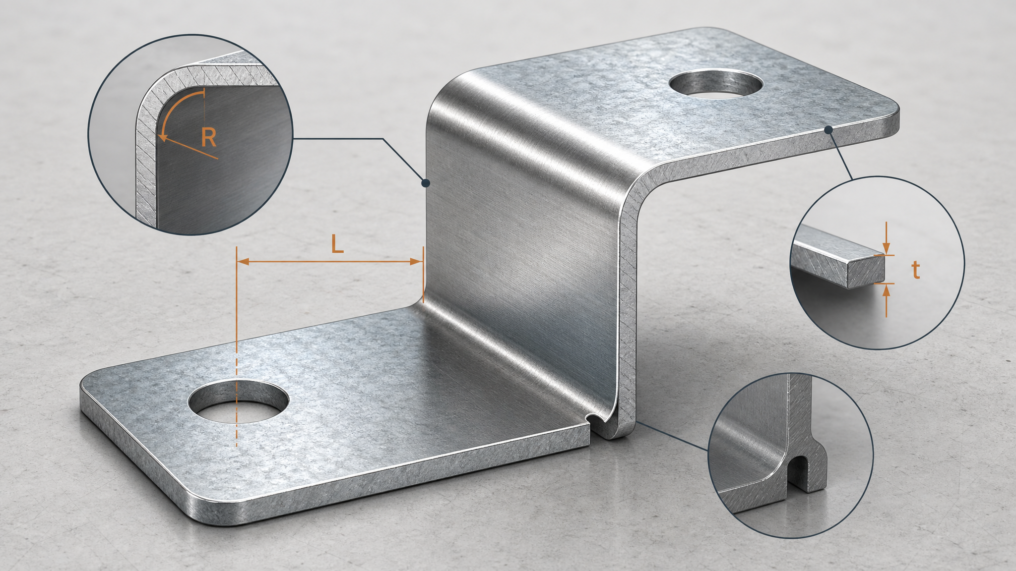
1. Critical Design Rules for Sheet Metal Bending
Bending is one of the most common sheet metal forming processes. Designing parts outside standard tooling radii causes tensile cracking along the outer fiber and excessive springback.
| Parameter / Feature | Recommended Design Rule | Minimum Limit | Engineering Rationale |
|---|---|---|---|
| Inside Bend Radius (R) | R = 1.0t to 1.5t | R ≥ 0.8t (Soft Al/Copper) | Prevents micro-fractures on outer bend surface; matches standard punch tools. |
| Hole-to-Bend Distance (L) | L ≥ 2.5t + R | L ≥ 2.0t + R | If holes are too close to bend line, stretching distorts round holes into ovals. |
| Minimum Flange Length (H) | H ≥ 4.0t + R | H ≥ 3.0t | Ensures the blank rests securely across V-die opening during press brake cycle. |
| Bend Relief Width (W) | W ≥ t or ≥ 1.5 mm | W ≥ 1.0 mm | Relieves corner stress at partial bends; prevents tearing at adjacent edges. |
| Bend Relief Depth (D) | D ≥ R + t | D ≥ R | Extends beyond tangent point of radius to eliminate material bunching. |
*Note: t = Material Sheet Thickness.
2. Punching, Hole Diameter, and Spacing Limits
Laser cutting can process fine apertures down to 0.5t, but progressive die stamping requires minimum punch diameters to avoid tool breakage.
| Feature Type | Stamping Rule | Laser Cutting Rule | Tooling / Quality Risk |
|---|---|---|---|
| Minimum Hole Diameter (d) | d ≥ 1.0t (Steel), d ≥ 1.2t (SS) | d ≥ 0.5t (Min 0.8 mm) | Punch pins buckle under high tonnage if d < t. |
| Hole-to-Edge Distance | ≥ 2.0t | ≥ 1.5t | Edge bulging and material breakout during piercing. |
| Hole-to-Hole Distance | ≥ 2.0t (Min 2.0 mm) | ≥ 1.5t | Web buckling between adjacent punched holes. |
| Slot-to-Bend Distance | ≥ 3.0t + R | ≥ 2.5t + R | Wall collapse along elongated slot profile. |
3. Manufacturing Tolerances: ISO 2768-m vs ISO 2768-f Comparison
Weizhi Hardware manufactures to ISO 2768-m (General Tolerances for Linear and Angular Dimensions) as standard. Tighter tolerances (ISO 2768-f or custom ±0.05 mm) can be maintained across critical datums.
| Nominal Dimension Range (mm) | ISO 2768-f (Fine / Precision) | ISO 2768-m (Medium / Standard) | Weizhi Achievable Precision |
|---|---|---|---|
| 0.5 to 3 mm | ±0.05 mm | ±0.10 mm | ±0.03 mm |
| 3 to 6 mm | ±0.05 mm | ±0.10 mm | ±0.05 mm |
| 6 to 30 mm | ±0.10 mm | ±0.20 mm | ±0.08 mm |
| 30 to 120 mm | ±0.15 mm | ±0.30 mm | ±0.10 mm |
| 120 to 400 mm | ±0.20 mm | ±0.50 mm | ±0.15 mm |
| 400 to 1000 mm | ±0.30 mm | ±0.80 mm | ±0.25 mm |
4. Engineering Checklist: 5 Tips to Cut Stamping & Fabrication Costs
- Standardize Bend Radii Across the Part: Using a single inside radius (e.g., R=1.5 mm) across all flanges eliminates tooling setup changes and secondary bending operations.
- Design Symmetrical or Fold-Nested Blanks: Symmetrical geometry improves blank nesting efficiency in sheet/coil raw material, boosting material utilization from 65% to over 85%.
- Incorporate Self-Locating Tabs and Slots: For welded assemblies, adding alignment tabs and slots eliminates expensive dedicated welding fixtures and ensures accurate position before robot TIG/MIG welding.
- Choose Commercial Standard Gauges: Avoid custom non-standard sheet thicknesses. Specify standard metric gauges (1.0, 1.2, 1.5, 2.0, 2.5, 3.0 mm) or standard imperial gauges.
- Consolidate Fasteners with Extruded Tapped Holes: For sheet thickness ≥ 1.5 mm, extruded holes with tapped threads can replace separate PEM clinch nuts, cutting hardware and assembly labor.
Frequently Asked Questions (FAQ)
What CAD formats are best for DFM review and rapid quoting?
We recommend submitting a 3D model in STEP (.step / .stp) or IGES (.igs) format alongside a 2D drawing in PDF or DWG/DXF. The 3D model allows our CAM software to unfold blank dimensions, while the 2D drawing defines critical tolerances, hole threads (e.g., M4x0.7), finish specifications, and quality inspection datums.
How do you handle springback in high-strength stainless steel and aluminum?
Springback is compensated during tool design through finite element analysis (FEA) simulation and empirical bottoming/overbending techniques. For progressive dies, our tooling engineers add dedicated coining or re-strike stations to lock in dimensional accuracy.
Can Weizhi provide a formal DFM feedback report before tooling begins?
Yes. Every new order and RFQ receives a complimentary engineering DFM review. Our engineers verify bend radii, hole spacing, draft angles, and raw material availability within 24 hours.